Engine Air intake and EXHAUST SYSTEMS
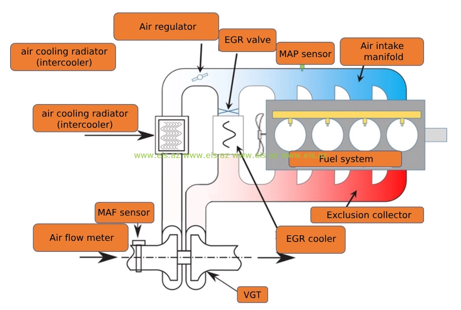
The engine air system consists of the following main parts.
- Air filter and connecting pipes
- Mass air flow meter (MAF)
- Turbocharger
- Intercooler
- Air regulator (mechanical and electronic)
- Boost pressure sensor
- Intake air temperature sensor
- Manifold pressure sensor (MAP)
- Air intake manifold
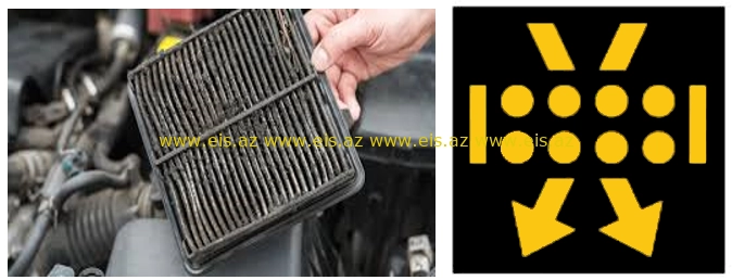
 Usually, engine failures start from simple parts (from simple to complex). The air filter is one of the most important parts in the engine, regardless of its simple and easy installation. A poor quality air filter or not replaced on time leads to a lack of air in the engine. At this time, it prevents the fuel injected into the cylinders from burning completely. This problem causes black fog or loss of power.
Generally, lack of air is caused by a clogged air filter, intercooler, any artificial obstruction in the air and exhaust circuit, or wear on the turbo.
Artificial obstacles include micro-cracks in the air pipes entering and exiting the engine, bodies formed inside the pipes, difficulties in the data transmission of the sensors placed on them, disrupting the air-fuel balance required by the piston and causing malfunctions.
Dirty air - dirty, dusty air entering the engine without good filtration causes serious malfunctions. Thus, serious wear and tear of pistons, piston rings, and sleeves increases.
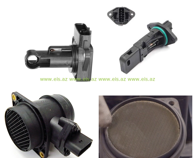
Mass Air Flow ( MAF )
The MAF sensor determines the air-fuel balance by measuring the amount of air entering the engine. Studying the intake air mass is more important for the ECM (engine control module). So sending the right amount of air fuel to the engine also depends on this sensor. Air density varies with temperature and pressure. This means that the vehicle and equipment are directly affected by ambient temperature and pressure. If the MAF sensor electronics are not clean (even though there is no fault code information) the air fuel balance will not be calculated correctly and engine performance will be poor.
Turbocharger and intercooler
This device, which works like an air pump, consists of a turbine and a compressor connected to the same shaft. The exhaust gases pass between the turbine blades and cause the turbine wheel to rotate. The exhaust gases drive the turbine and therefore the compressor wheel and reach a high speed of between 30,000 and 130,000 rpm (may be higher on different engines). This allows compressed air to be inhaled. When the load on the engine increases, more fuel is sent to the cylinders. Increased combustion produces more exhaust gas, allowing the turbine and compressor to spin faster. As the compressor wheel rotates faster, more air is drawn into the engine.
The turbo system has a number of important advantages:
1. Power - Compressed air contains more oxygen per unit volume. More oxygen filling the cylinder allows more fuel to be burned to produce higher power.
2. Efficiency - A turbocharged system provides more efficient combustion for better emissions and fuel economy.
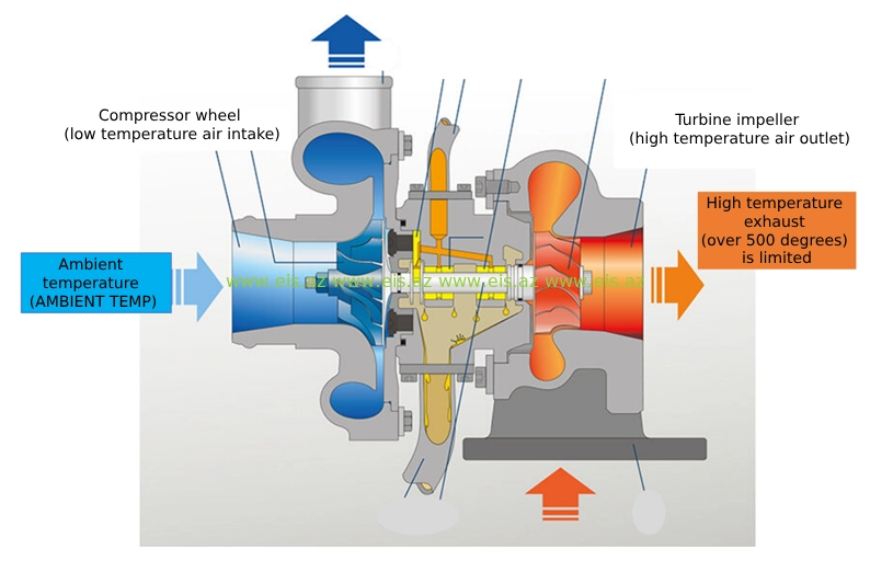
When the turbo compresses the intake air, the temperature of the air rises. Since warm air is less dense, it contains less oxygen. If hot compressed air is sent to the engine, the efficiency gained by compression is lost. The air cooling radiator is used together with the turbo. Thus, the air flow passing through the turbo is cooled before entering the cylinder. This allows the air to condense and contain more oxygen per unit volume. Increasing the amount of oxygen in the cylinders means the engine is more powerful and efficient.
Every 1 °C increase in the intake air temperature causes a 3 °C increase in the exhaust gas temperature. For example: An engine without an air-cooled radiator operating at full load with an ambient temperature of 21 °C and an air inlet manifold pressure of 117 kPa has an intake manifold air temperature of approximately 120 °C and an exhaust gas temperature of 621.1 °C. However, if the same engine has an air cooling radiator, the intake manifold air temperature is approximately 87.7 °C and the exhaust gas temperature is 537.7 °C.
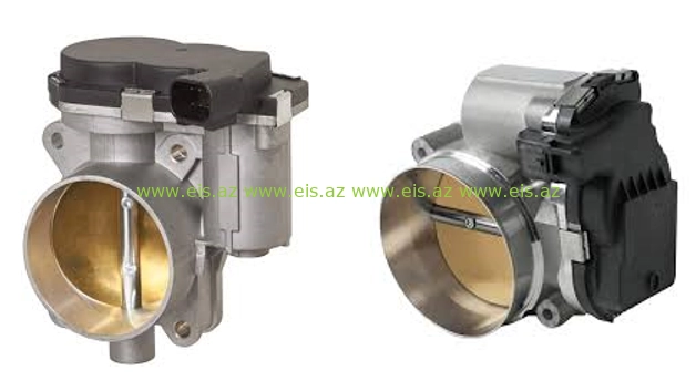
Air regulator (mechanical and electronic)
Air regulator (body throttle, shutter) - adjusts the amount of air flow to the engine at the moment it is needed. In gasoline engines, it works by opening the path of air entering the engine, while in diesel engines, it works by closing the path of air entering the engine. In both groups of engines, if this part is not clean, the engine will run erratically. Cleaning is recommended every 30,000 km.
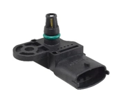
 Boost pressure sensor and MAP sensor
Both sensors are placed on the air intake manifold. MAP is usually found on non-turbo engines and measures the pressure in the intake manifold.
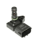 The boost pressure sensor (turbocharger pressure) is located in the air intake manifold and measures the pressure created by the turbo in the manifold. It also controls the boost position of the turbocharger.
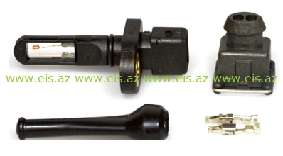
Intake air temperature sensor
The temperature indicator in the air intake collector sends the temperature of the air entering the collector and the voltage signals generated due to this heat to the electronic module. The indicated signal indicators affect the air-fuel mixture and the ignition angle. So, there is a certain dependence between the temperature in the air intake manifold and the temperature of the outside air. If the temperature in the inlet collector exceeds 1 °C, the air temperature in the outlet collector increases by 3 degrees. If there is any artificial resistance in the air intake manifold and pipes, the standard temperature reading in the direct outlet manifold will be higher. At this time, modern engines immediately protect themselves and the engine works in emergency mode. Artificial resistance refers to institutions that prevent the movement of air flow in the intake manifold. Although a certain part of the work is solved by cleaning the institutions, the main fault that created these institutions should be identified. The resistance of the temperature sensor varies depending on the temperature of the incoming air. As the temperature increases, the resistance decreases, which reduces the voltage across the sensor. The control unit evaluates these voltage values. Because they are directly related to the inlet air temperature (low temperatures lead to high voltage values at the sensor, and high temperatures to low voltage values).
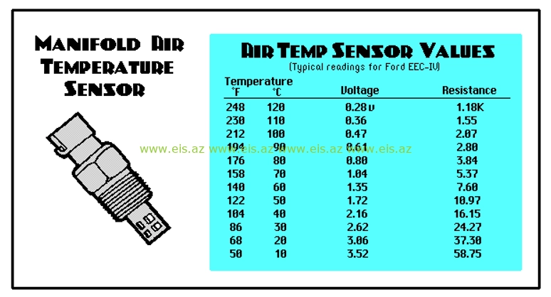
As can be seen from the table above, when looking at the IAT indicators during diagnosis, it is known that as the temperature of the incoming air increases, the voltage decreases, and the resistance increases. That is, at 10 °C the voltage is 3.52 V, and the resistance is 58.75 Ohm, at 120 °C the voltage is 0.28 V, and the resistance is 1.18 OM.
The IAT sensor works like an engine coolant temperature sensor. If the IAT sensor is not working properly, the air/fuel mixture in the engine will be different. Thus, the engine will not have the necessary air/fuel mixture when cold, and the engine will not run regularly and fuel consumption will increase.
When diagnosing the IAT sensor, you can compare it to the engine cooling sensor, that is, how it reacts as the temperature increases.
The IAT sensor should not be 10 °F (-12 °C) below or above ambient temperature. If it is not, then there is a malfunction in this part of the engine. - 40 °C (F) or lower, then the part is faulty. Disconnect the IAT sensor connector and you should see -30,-40 °C on the scanner. If you do not see this, then there is a malfunction in the electronics of the car. Make a jumper between the 2 wires of the IAT sensor, you should see 149 °C ( 300 F ), if you don't, either the wire or the electronics are bad. If the resistance is in the range of 0 ~ 47 Ohm, the IAT is faulty.

Qonaqlar bu nəşrə şərh yaza bilməz.