Тут будет текст
Nasazlıqların yaranma səbəbi
Burada Nasazlıqların Yaranma Səbəbi hissəsi barədə mətn yerləşdiriləcək
Electronic control unit (Brain)
Modern engines are equipped with specially programmed control modules that monitor and analyze all processes in the engine and ensure smooth, regular operation of the engine in accordance with the indicators.
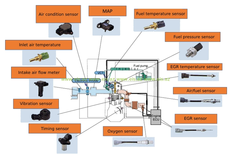
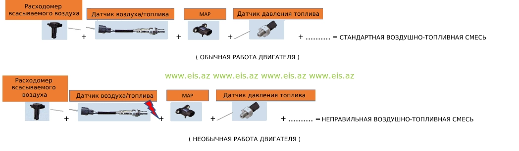
As you can see from the picture above, when there is a malfunction in the engine system, the control module receives information from that malfunctioning part. In this case, the driver is reflected in the information panel or there are such malfunctions that it does not indicate as a malfunction, the engine works irregularly. This means that the data transmitted to the control module is not compatible with the data of other indicators. In this case, the electronic module will try to start the engine based on the results of the matching and non-matching data.
This type of malfunctions can be due to dirty sensors, faulty sensor, malfunctions in mechanical parts, low conductivity in electrical cables and many other reasons. A thorough inspection of the vehicle means that it will last even longer.
Particulate filter (DOC, DPF, SCR, Сatalyzer)
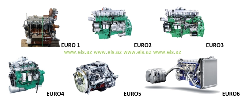
As technology develops, negative effects on the environment are increasing. At this time, measures were taken to prevent the impact of toxic gases from engines on the atmosphere in order to protect the ecological balance. The engines are named EURO 1,2,3,4,5,6 according to their emission levels, and the engine systems are further developed in each ascending sequence.
 As a result, the amount of toxic gases released was reduced and the atmosphere was protected. Here, the first main point was the preparation of the emission system by the factory, and the second, more serious point was that it depends on the person using the vehicle, equipment, unit. Engine systems must be serviced periodically as required by the manufacturer. Otherwise, malfunctions occur and the negative impact of exhaust gases on the atmosphere increases. Pollution of the atmosphere with toxic gases causes the short life of whatever is alive in nature.
So, the topic is control of the manufacturer's parameters of exhaust gases from the engine, their verification and troubleshooting.
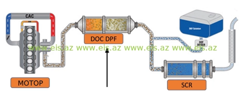
 Engine to DOC: After leaving the engine, the exhaust gases first enter the Diesel Oxidation Catalyst.
DOC Stage: Here, harmful gases such as carbon monoxide (CO) and hydrocarbons (HC) are oxidized to less harmful carbon dioxide (CO2) and water (H2O). This process also increases the temperature of the exhaust gas and helps in the subsequent DPF stage.
DPF Stage: The heated gases then flow to the Diesel Particulate Filter, where soot and soot are captured and burned periodically during regeneration.
SCR Stage: After particulate filtration, the gases pass to the Selective Catalytic Reduction unit. As you can see from the picture above, toxic gases pass through several parts before being released into the atmosphere, reducing the level of toxicity. In this regard, the parts that must be checked to ensure that the gases coming out of the engines are within the factory standard are listed below:
- Fuel tank cleanliness
- Timely replacement of fuel filters
- Stand of fuel injectors
- High pressure pump stand
- Timely replacement of the air filter
- Checking the condition of the air pipes
- Checking and cleaning the air cooler radiator
- Visual inspection of the turbocharger
- Cleanliness of measurement sensors on the air line (temperature, pressure)
- Cleaning the air intake manifold
- EGR inspection and cleaning
If the mentioned parts are not serviced on time, there will be serious malfunctions in the output part of the engine. In this case, it can lead to engine failure.
Engine Air intake and EXHAUST SYSTEMS
The engine air system consists of the following main parts.
- Air filter and connecting pipes
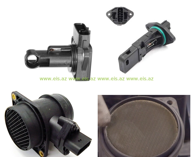
- Mass air flow meter (MAF)
- Turbocharger
- Intercooler
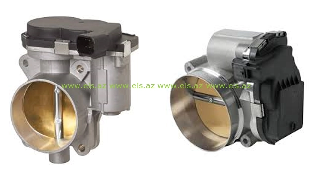
- Air regulator (mechanical and electronic)
- Boost pressure sensor
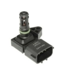
- Intake air temperature sensor
- Manifold pressure sensor (MAP)
- Air intake manifold
 Usually, engine failures start from simple parts (from simple to complex). The air filter is one of the most important parts in the engine, regardless of its simple and easy installation. A poor quality air filter or not replaced on time leads to a lack of air in the engine. At this time, it prevents the fuel injected into the cylinders from burning completely. This problem causes black fog or loss of power.
Generally, lack of air is caused by a clogged air filter, intercooler, any artificial obstruction in the air and exhaust circuit, or wear on the turbo.
Artificial obstacles include micro-cracks in the air pipes entering and exiting the engine, bodies formed inside the pipes, difficulties in the data transmission of the sensors placed on them, disrupting the air-fuel balance required by the piston and causing malfunctions.
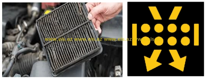
Dirty air - dirty, dusty air entering the engine without good filtration causes serious malfunctions. Thus, serious wear and tear of pistons, piston rings, and sleeves increases.
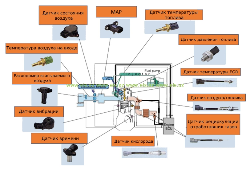
Mass Air Flow ( MAF )
The MAF sensor determines the air-fuel balance by measuring the amount of air entering the engine. Studying the intake air mass is more important for the ECM (engine control module). So sending the right amount of air fuel to the engine also depends on this sensor. Air density varies with temperature and pressure. This means that the vehicle and equipment are directly affected by ambient temperature and pressure. If the MAF sensor electronics are not clean (even though there is no fault code information) the air fuel balance will not be calculated correctly and engine performance will be poor.
Turbocharger and intercooler
This device, which works like an air pump, consists of a turbine and a compressor connected to the same shaft. The exhaust gases pass between the turbine blades and cause the turbine wheel to rotate. The exhaust gases drive the turbine and therefore the compressor wheel and reach a high speed of between 30,000 and 130,000 rpm (may be higher on different engines). This allows compressed air to be inhaled. When the load on the engine increases, more fuel is sent to the cylinders. Increased combustion produces more exhaust gas, allowing the turbine and compressor to spin faster. As the compressor wheel rotates faster, more air is drawn into the engine.
The turbo system has a number of important advantages:
1. Power - Compressed air contains more oxygen per unit volume. More oxygen filling the cylinder allows more fuel to be burned to produce higher power.
2. Efficiency - A turbocharged system provides more efficient combustion for better emissions and fuel economy.
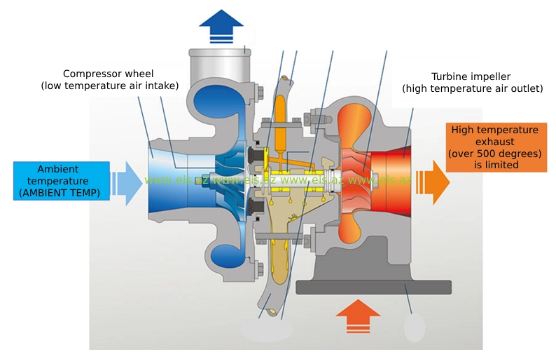
When the turbo compresses the intake air, the temperature of the air rises. Since warm air is less dense, it contains less oxygen. If hot compressed air is sent to the engine, the efficiency gained by compression is lost. The air cooling radiator is used together with the turbo. Thus, the air flow passing through the turbo is cooled before entering the cylinder. This allows the air to condense and contain more oxygen per unit volume. Increasing the amount of oxygen in the cylinders means the engine is more powerful and efficient.
Every 1 °C increase in the intake air temperature causes a 3 °C increase in the exhaust gas temperature. For example: An engine without an air-cooled radiator operating at full load with an ambient temperature of 21 °C and an air inlet manifold pressure of 117 kPa has an intake manifold air temperature of approximately 120 °C and an exhaust gas temperature of 621.1 °C. However, if the same engine has an air cooling radiator, the intake manifold air temperature is approximately 87.7 °C and the exhaust gas temperature is 537.7 °C.
Air regulator (mechanical and electronic)
Air regulator (body throttle, shutter) - adjusts the amount of air flow to the engine at the moment it is needed. In gasoline engines, it works by opening the path of air entering the engine, while in diesel engines, it works by closing the path of air entering the engine. In both groups of engines, if this part is not clean, the engine will run erratically. Cleaning is recommended every 30,000 km.
 Boost pressure sensor and MAP sensor
Both sensors are placed on the air intake manifold. MAP is usually found on non-turbo engines and measures the pressure in the intake manifold.
 The boost pressure sensor (turbocharger pressure) is located in the air intake manifold and measures the pressure created by the turbo in the manifold. It also controls the boost position of the turbocharger.
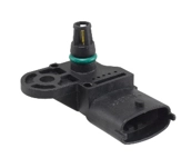
Intake air temperature sensor
The temperature indicator in the air intake collector sends the temperature of the air entering the collector and the voltage signals generated due to this heat to the electronic module. The indicated signal indicators affect the air-fuel mixture and the ignition angle. So, there is a certain dependence between the temperature in the air intake manifold and the temperature of the outside air. If the temperature in the inlet collector exceeds 1 °C, the air temperature in the outlet collector increases by 3 degrees. If there is any artificial resistance in the air intake manifold and pipes, the standard temperature reading in the direct outlet manifold will be higher. At this time, modern engines immediately protect themselves and the engine works in emergency mode. Artificial resistance refers to institutions that prevent the movement of air flow in the intake manifold. Although a certain part of the work is solved by cleaning the institutions, the main fault that created these institutions should be identified. The resistance of the temperature sensor varies depending on the temperature of the incoming air. As the temperature increases, the resistance decreases, which reduces the voltage across the sensor. The control unit evaluates these voltage values. Because they are directly related to the inlet air temperature (low temperatures lead to high voltage values at the sensor, and high temperatures to low voltage values).
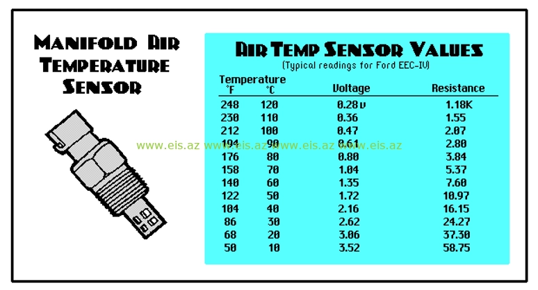
As can be seen from the table above, when looking at the IAT indicators during diagnosis, it is known that as the temperature of the incoming air increases, the voltage decreases, and the resistance increases. That is, at 10 °C the voltage is 3.52 V, and the resistance is 58.75 Ohm, at 120 °C the voltage is 0.28 V, and the resistance is 1.18 OM.
The IAT sensor works like an engine coolant temperature sensor. If the IAT sensor is not working properly, the air/fuel mixture in the engine will be different. Thus, the engine will not have the necessary air/fuel mixture when cold, and the engine will not run regularly and fuel consumption will increase.
When diagnosing the IAT sensor, you can compare it to the engine cooling sensor, that is, how it reacts as the temperature increases.
The IAT sensor should not be 10 °F (-12 °C) below or above ambient temperature. If it is not, then there is a malfunction in this part of the engine. - 40 °C (F) or lower, then the part is faulty. Disconnect the IAT sensor connector and you should see -30,-40 °C on the scanner. If you do not see this, then there is a malfunction in the electronics of the car. Make a jumper between the 2 wires of the IAT sensor, you should see 149 °C ( 300 F ), if you don't, either the wire or the electronics are bad. If the resistance is in the range of 0 ~ 47 Ohm, the IAT is faulty.
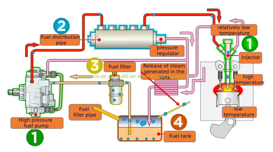
Engine-Fuel SYSTEM
The engine fuel system consists of a fuel tank, filter, pressure regulator, fuel distribution pipe, injectors and pipes that transfer fuel to these parts.
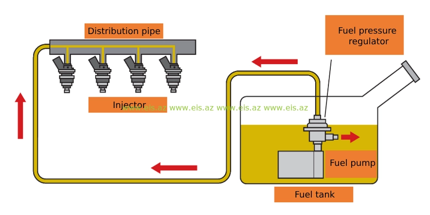
When the fuel tank is used for a long time with empty or less than half fuel, water accumulates as a result of condensation and causes malfunctions in the fuel system (detail - in the section on the cause of malfunctions). This process can be followed in the following way:
- Injector location in engine
- 3rd stroke high temperature (Suitable for 4 stroke engines)
- Relatively low temperature fuel return (pink color)
- Pink color is the part that enters the fuel tank (low temperature)
- The fuel entering the fuel tank from the return of the injector is at a higher temperature than the fuel in the tank
- At this time, there is a temperature difference and steam is formed (for example, steam from the mouth and nose of people in cold weather)
- Considering that the upper layer of the fuel tank is in direct contact with the atmosphere, the atmospheric temperature has a direct effect on this process
- In order to exhaust the vapor generated in the fuel tank, it is released to the atmosphere or to the air intake manifold of the engine (in diesel engines to the atmosphere, in gasoline engines to the engine) through the exhaust pipe located in the upper part of the tank, from the fuel filler pipe
- If there is any malfunction in the steam discharge pipe or line, then the steam generated at this time cannot be discharged, and as a result of the change in atmospheric temperature (night, day), the process of passing steam into liquid, i.e., condensation occurs
- Condensation is the transition of steam to liquid (the steam coming out of the kettle in the form of steam turns into liquid on the wall surface). In this case, steam turns into water
- It is known from physics that the density of water is greater than the density of fuel. So the water sinks to the bottom of the fuel tank and enters the fuel system. The fuel filter reflects the water entering the driver information panel (in some cases, the water trap sensor on the fuel filter is faulty and drivers do not notice it)
The fuel filter retains the incoming water, so if it is not changed in time, it is gradually transferred to the fuel pump and injectors. At this time, serious malfunctions occur in the fuel system. In the picture below, it is possible to visually see the passage of water into the fuel line.
Electronic and Mechanical DIAGNOSTICS
- Computer diagnostics
Checks electrical lines and electronic modules of engine, chassis, body parts by means of special programs and equipment of vehicles and equipment.
Example - a fault detected in the diagnostic program indicates that the electrical indicator of the engine cooling system (coolant sensor) does not work.
- Mechanical diagnostics
It is a mechanical inspection using special tools based on computer diagnostic results.
Example - The engine cooling system sensor check sequence (checking the sensor itself, the electrical line, the electronic control module, and finally the cooling system) found in the diagnostic program. As a result, the diagnostician gives a direct direction to eliminate the malfunction.
NOTE: In some cases, the computer does not show any information about the malfunction during diagnostics. In such a situation, the diagnostician must know the principle of operation of the vehicle, otherwise it is impossible to determine the fault.
Электронный блок управления (Мозг)
Современные двигатели оснащены специально запрограммированными модулями управления, которые контролируют и анализируют все процессы в двигателе и обеспечивают плавную, регулярную работу двигателя в соответствии с показателями.
 Как видно из рисунка выше, при возникновении неисправности в системе двигателя модуль управления получает информацию от этой неисправной детали. В этом случае на информационной панели водителя отражается или возникают такие неисправности, которые он не указывает как неисправность, двигатель работает неравномерно. Это означает, что данные, передаваемые в модуль управления, несовместимы с данными других индикаторов. В этом случае электронный модуль попытается запустить двигатель по результатам совпадающих и несовпадающих данных.
Этот тип неисправностей может быть вызван загрязнением датчиков, неисправностью датчика, неисправностью механических частей, низкой проводимостью электрических кабелей и многими другими причинами. Тщательный осмотр автомобиля означает, что он прослужит еще дольше.
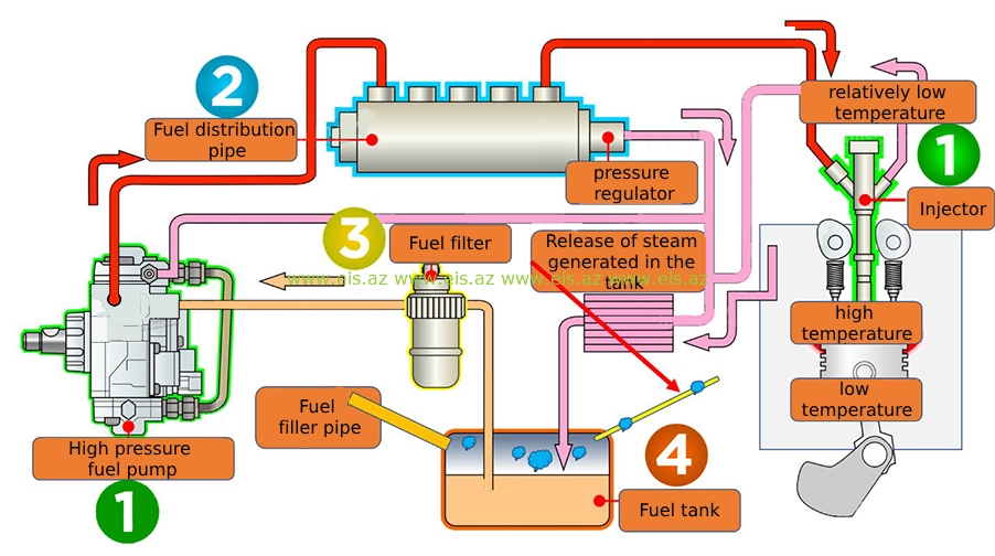
Сажевый фильтр (DOC, DPF, SCR, Катализатор)
По мере развития технологий негативное воздействие на окружающую среду увеличивается. В это время были приняты меры по предотвращению воздействия токсичных газов двигателей на атмосферу с целью защиты экологического баланса. Двигатели получили названия EURO 1,2,3,4,5,6 в зависимости от уровня выбросов, а системы двигателя совершенствуются в каждой возрастающей последовательности.
 В результате количество выделяемых токсичных газов сократилось, а атмосфера была защищена. Здесь первым основным моментом была подготовка системы выбросов на заводе, а вторым, более серьезным моментом, было то, что это зависит от человека, использующего транспортное средство, оборудование, агрегат. Системы двигателя необходимо периодически обслуживать в соответствии с требованиями производителя. В противном случае возникают неисправности и усиливается негативное воздействие выхлопных газов на атмосферу. Загрязнение атмосферы токсичными газами приводит к короткой жизни всего живого в природе.
Итак, тема - контроль заводских параметров выхлопных газов двигателя, их проверка и устранение неисправностей.
 Из двигатель в DOC: После выхода из двигателя выхлопные газы сначала попадают в катализатор окисления дизельного топлива.
Стадия DOC: Здесь вредные газы, такие как окись углерода (CO) и углеводороды (HC), окисляются до менее вредного диоксида углерода (CO2) и воды (H2O). Этот процесс также повышает температуру выхлопных газов и помогает на последующей стадии DPF.
Этап DPF: нагретые газы затем поступают в сажевый фильтр, где сажа и сажа улавливаются и периодически сжигаются во время регенерации.
Этап SCR: после фильтрации твердых частиц газы поступают в установку селективного каталитического восстановления. Как видно на картинке выше, токсичные газы проходят через несколько частей, прежде чем попасть в атмосферу, снижая уровень токсичности. В связи с этим ниже перечислены детали, которые необходимо проверить на предмет соответствия газов, выходящих из двигателей, заводскому стандарту:
- Чистота топливного бака
- Своевременная замена топливных фильтров
- Стенд топливных форсунок
- Стенд насоса высокого давления
- Своевременная замена воздушного фильтра
- Проверка состояния воздуховодов
- Проверка и чистка радиатора воздухоохладителя
- Визуальный осмотр турбокомпрессора
- Чистота измерительных датчиков на воздушной магистрали (температура, давление)
- Чистка впускного коллектора
- Проверка и чистка EGR
Если указанные детали не обслуживать вовремя, возникнут серьезные неисправности в выходной части двигателя. В этом случае это может привести к выходу двигателя из строя.